A single-phase synchronous Reluctance Motor is basically the same as the single cage type induction motor. The stator of the motor has the main and auxiliary winding. The stator of the single-phase reluctance and induction motor is the same. The rotor of a reluctance motor is a squirrel cage with some rotor teeth removed in certain places to provide the desired number of salient rotor poles.
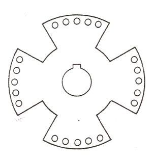
The figure below shows the 4 pole reluctance type synchronous motor.
In the above figure, the teeth have been removed in four locations to produce a 4 pole structure. The two end rings are short-circuited. When the stator is connected to a single-phase supply, the motor starts as a single-phase induction motor. A centrifugal switch disconnects the auxiliary winding as soon as the speed of the motor reaches about 75% of the synchronous speed. The motor continues to speed up as a single-phase motor with the main winding in operation.
A reluctance motor torque is produced due to the tendency of the rotor to align itself in the minimum reluctance position when the speed of the motor is close to the synchronous speed. Thus, the rotor pulls in synchronism. The load inertia should be within the limits, for proper effectiveness. At synchronism, the induction torque disappears, but the rotor remains in synchronism due to synchronous reluctance torque.
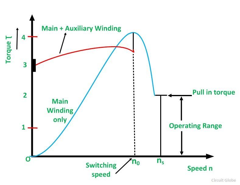
The Torque Speed Characteristic of a single-phase Reluctance Motor is shown below:
The starting torque depends upon the rotor position. The value of the starting torque varies between 300 to 400 % of its full load torque. As we know that as the motor attains speed nearly of synchronous speed the auxiliary winding is disconnected and the rotor continues to rotate at the synchronous speed.
The motor operates at a constant speed up to a little over 200% of its full load torque. If the loading of the motor is increased above the value of the pull-out torque, the motor loses synchronism but continues to run as a single phase induction motor up to over 500% of its rated torque.
In the starting, the motor is subjected to Cogging. This can be reduced by skewing the rotor bars and by having the rotor slots not exact multiples of the number of poles.
The rotor of a Reluctance Motor is unexcited, therefore, the power factor is low as compared to the induction motor. As the motor has no DC field excitation so the output of a reluctance motor is reduced. Hence, the size of the motor is large as compared to the synchronous motor.
Applications of a Reluctance Motor
The various applications of the Reluctance Motor are as follows:
- Simple construction as there are no slip rings, no brushes, and no DC field windings.
- Low cost
- Maintenance is easy.
- It is used for many constant speed applications such as electric clock timers, signaling devices, recording instruments, etc.
This is all about Reluctance Motor.


Superb explanation